Neuro Parameters– Record EEG, EOG, EMG– Required for Sleep Staging and Scoring Arousals. EEG, EOG and Chin EMG is also recorded during MSLT and MWT in addition to ECG.
A. ElectroEncephalography (EEG)- Electrodes are placed following 10-20 International EEG electrode placement System (Fig:15)
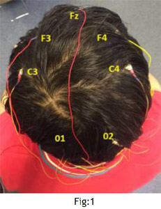
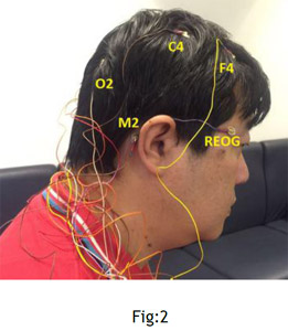
Recommended Leads for Sleep EEG– F4-M1, C4-M1, O2-M1 (Fig:1 and Fig:2)
Backup Leads– F3-M2, C3-M2, O1-M2 (Fig:1)
M1 and M2 are Reference leads– Placed on left and right Mastoid process behind ear respectively (Fig:2)
B. Electrooculogram (EOG) (Fig:3)
Right Electrooculogram (REOG). Also called E2
Left Electrooculogram (LEOG). Also called E1
REOG is placed 1cm above outer canthus
LEOG is placed 1cm below outer canthus
Referenced to M2. (E1-M2 & E2-M2)
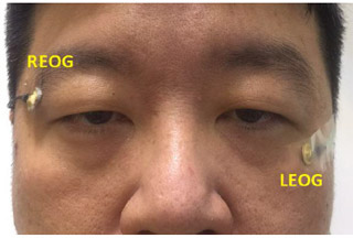
Fig: 3
C. Chin Electromyogram (EMG) (Fig: 4)
one electrode is placed in the midline 1 cm above the inferior edge of the mandible;
one electrode placed 2 cm below the inferior edge and 2 cm to the left of the midline;
one electrode placed 2cm below the inferior edge and 2 cm to the right of the midline.
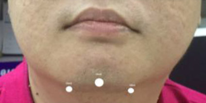
Fig: 4
Respiratory Parameters– Measure Airflow, Respiratory Effort, Snore, Oxygen Saturation. Home Sleep Testing (HST) measure Respiratory parameters only or Respiratory parameters plus ECG.
A. Airflow– Measured using both Thermistor (Fig:5) and Pressure Transducer (Fig:6)in Level 1 Sleep study. In HST you can use either Thermistor or Pressure Transducer.
During CPAP/BiPAP titration airflow is measured from PAP machine and we do not place Thermistor and Pressure transducer cannula under the mask.
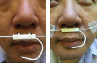
Fig:5 Thermistor- Used to score Apnea
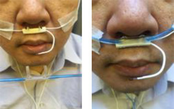
Fig:6 Pressure Transducer Cannula- Used to score hypopnea
B. Respiratory Effort– Two Belts (Fig: 7), one on Thorax at nipple level and One on abdomen at naval level. Belts use Respiratory Inductance Plethysmography (RIP) technology. In HST only one belt is acceptable.
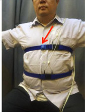
Fig:7 Thoracic and Abdominal belts and Body Position sensor (Red Arrow)
C. Snore Sensor- The snore sensor is placed over the trachea or on the side of the neck and secured with tape. In HST, snoring is recorded by pressure transducer cannula.
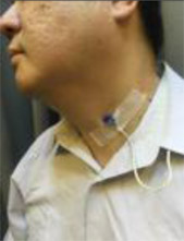
Fig:8 Snore sensor
D. Oxygen Saturation– Use Finger pulse Oximeter probe
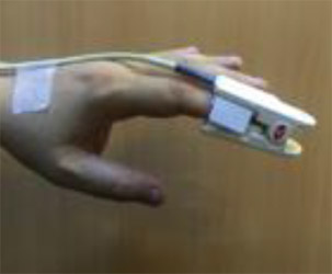
Fig: 9 Finger Pulse Oximeter probe
Electrocardiogram (ECG)- Recorded from lead-II. Two electrodes placed 2cm below left and right clavicle and one electrode on lower rib cage in midclavicular line
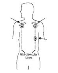
Fig:10 ECG Electrode placement
Leg EMG- Two electrodes are placed longitudinally on the anterior tibialis muscle of each leg 2-3 cm apart and secured with tape to record each leg activity separately.
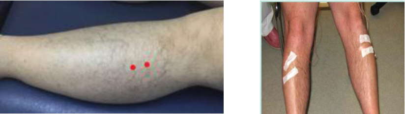
Fig: 11 Leg EMG Electrodes
10-20 International EEG Electrode Placement System
Step– 1 Locate Nasion– Junction of nose with forehead
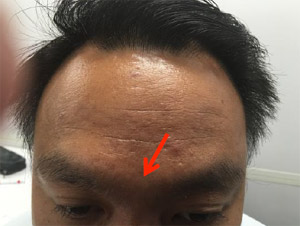
Fig:12 Locating Nasion (Red Arrow)
Step– 2 Locate Inion (Occipital Protuberance)– at back of head
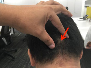
Fig: 13 Locating Inion (Red Arrow)
Step– 3 Locate left and right Preauricular point– In front of tragus of ear
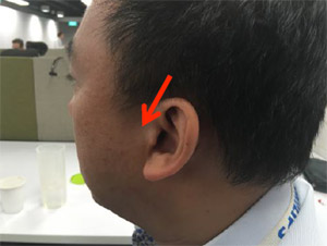
Fig:14 Locating left pre-auricular point (Red Arrow)
Step– 4 Measure distance from Nasion to Inion in cm
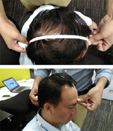
Step-5 (Fig: 15 Red Line)
Measure distance from Nasion to Inion
- Mark 10% of the total distance up from the nasion as (Fpz) and from inion as (Oz) along the line joining them.
- Mark the halfway point between nasion and inion as (Cz).
- Mark 20% of the total distance from Cz in front as (Fz) and back as (Pz) along the line joining the nasion and inion.
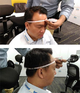
Step-6 Measure distance from left to right pre-auricular point going through Cz
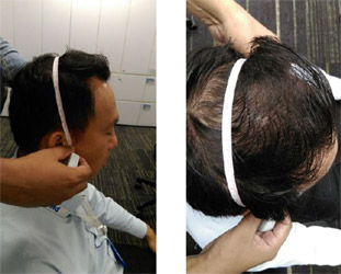
Step 7 (Fig:15 Blue Line)
- Measure the distance from the left pre-auricular point to the right preauricular point, with the tape passing through Cz
- Mark 10% of this distance up from the left preauricular point as (T3) and right preauricular point as (T4).
- From Cz mark 20% of this distance on left as (C3) and right as (C4) side on the line joining the left and right preauricular points
Step-8 Measure the circumference of head going through FpZ, T3, Oz, T4 and back to FpZ
Step-9 (Fig:15 Green Circle)
- Measure the circumference of the head.
- The measuring tape should pass through FpZ, T3, Oz, T4 and FpZ
- Mark 5% of the circumference on the left and right of Fpz as (Fp1 and Fp2) and Oz as (O1 and O2)
- Mark 10% of the circumference to the left of Fp1 as (F7) and right of Fp2 as (F8)
- Mark 10% of the circumference to the left of O1 as (T5) and right of O2 as (T6)
Step-10 (Fig:15 Brown Line)
- Measure from Fp1 to O1 passing through C3
- Mark 25% of this distance on the line joining Fp1 and C3 from Fp1 as F3
- Mark 25% of this distance on the line joining O1 and C3 from O1 as P3
- Measure from Fp2 to O2 passing through C4
- Mark 25% of this distance on the line joining Fp2 and C4 from Fp2 as F4
- 25% of this distance on the line joining O2 and C4 from O2 as P4
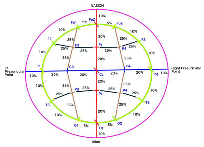
Fig:15 10-20 International EEG electrode placement system